Smallest viable MicroPython Computer?
Dallas Semiconductor, acquired by Maxim Integrated in 2002, was a company that designed and manufactured analog, digital, and mixed-signal semiconductors. They had also designed the TINI board, a 68-pin SIMM, approximately 103 mm wide, 32mm tall, and 10 mm thick. Uniquely, the TINI board ran Java programs, well Java byte-code, almost natively.
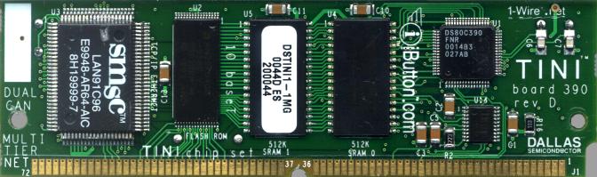
Dallas Semiconductor is no more nor does anyone wants to run their Java programs natively on hardware anymore. However, back in 2001, I found this idea intriguing and it sparked an interest to learn much more about hardware.
Today, running MicroPython on ESP32 modules seems to re-envision the idea to execute software developed in a high-level programming language almost natively on hardware. I.e., letting Python programs directly interact with hardware components.
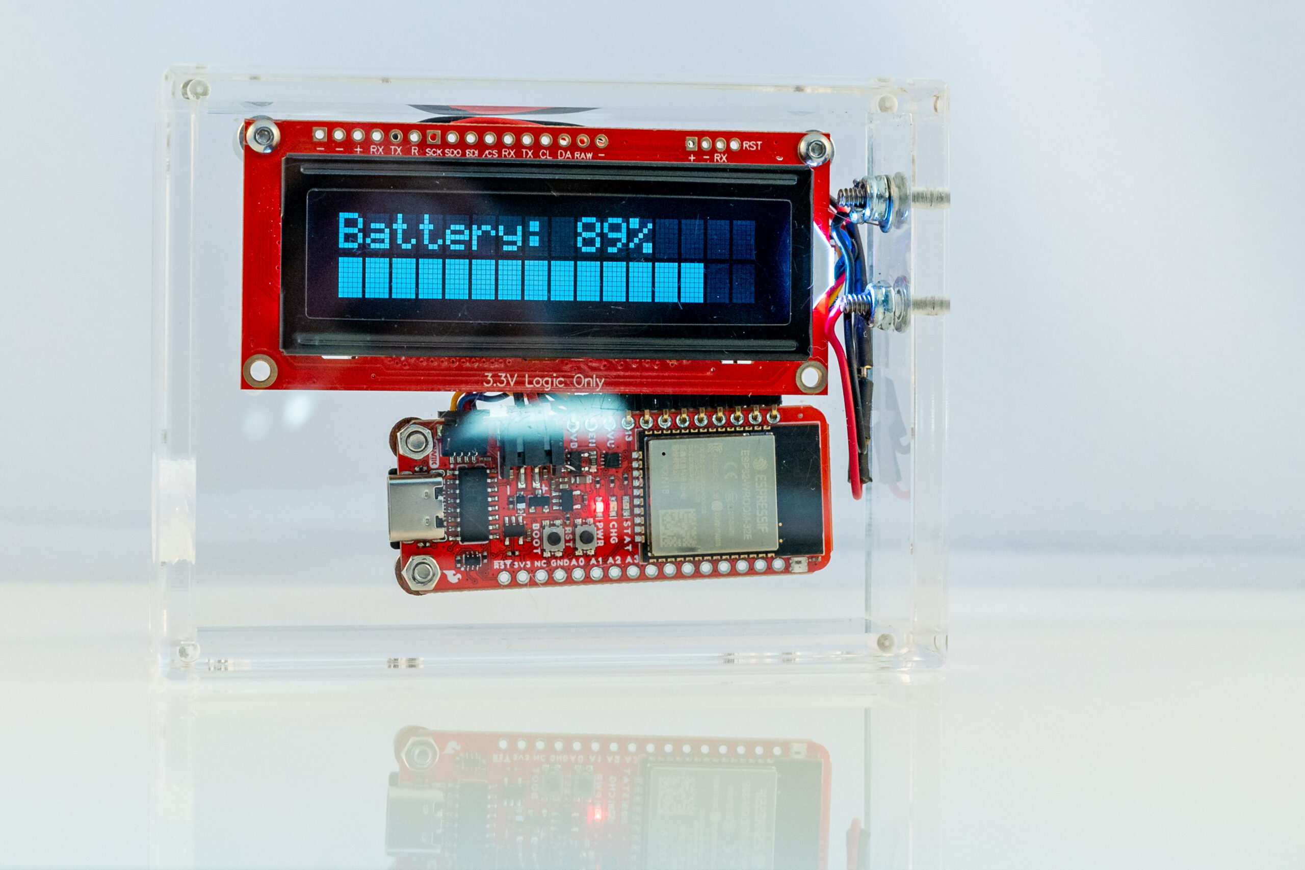
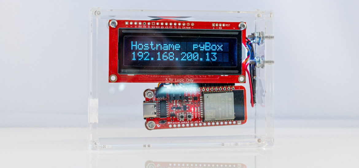
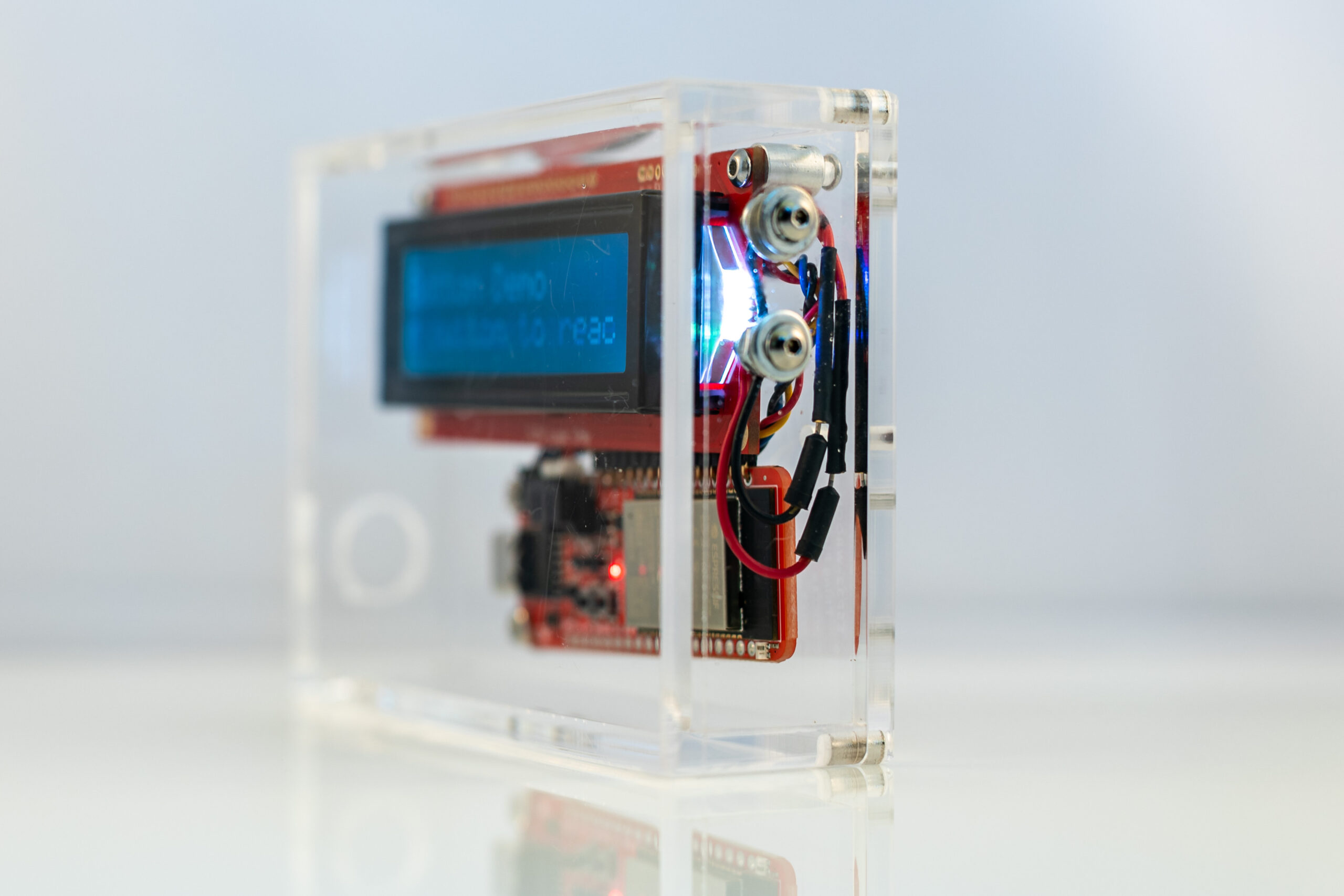
Traditionally, a computer has input and output devices (like a keyboard and monitor), allowing users to communicate with the machine. The pyBox, an ESP32-powered device, can connect to WiFi and Bluetooth, has a rather limited 16×2 character display, and only two capacitive buttons, but may still be one of the smallest viable MicroPython Computers.

People who are really serious about software should make their own hardware. -Alan Kay in July 1982
Bill Of Material
- SparkFun Thing Plus – ESP32 WROOM (USB-C) – $25
- SparkFun 16×2 SerLCD – RGB Text (Qwiic) – $22
- Qwiic Cable – 50mm – $1
- Enclosure:
- 4 Standoffs/Spacers, metal screws, nuts $4
- 2 capacitive buttons $4
- 2 metal screws, washers, and nuts
- 2 right angle mounting, male pin headers
- 2 female connector wires for headers
- USB-C cable – $10
- MicroSD Card (optional) – $10
- Lithium Ion Battery 3.7V 500 to 1000mAh (optional) – $10
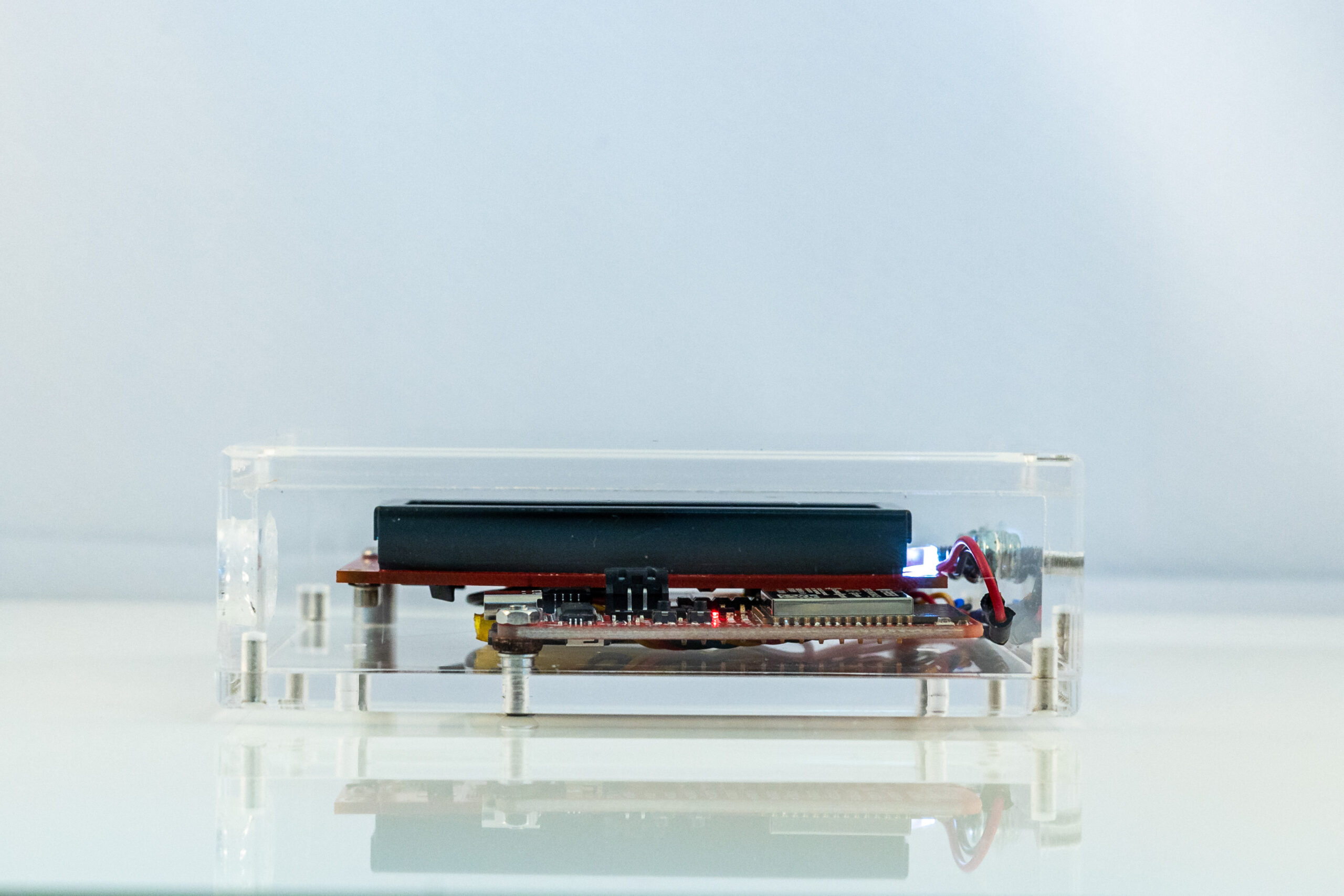
Hardware Assembly
Putting together the hardware components is rather simple. After drilling four small holes into the back plate of the acrylic case, the standoffs can be put into place, allowing the ESP32 board and the LCD to be mounted.
Providing power and connectivity, the Qwiic cable connects the LCD to the board. Headers need to be soldered onto I/O pins 27 and 33 and connected to metal screws drilled into one side of the acrylic enclosure.
Finally, a bigger hole needs to be drilled into the other of the case, just big enough for a USB-C connector to pass through.
Hardware Components
SparkFun Thing Plus
The SparkFun Thing Plus features the common dual-core ESP32-D0WDQ6 chip of the initial production release of the ESP32 series.
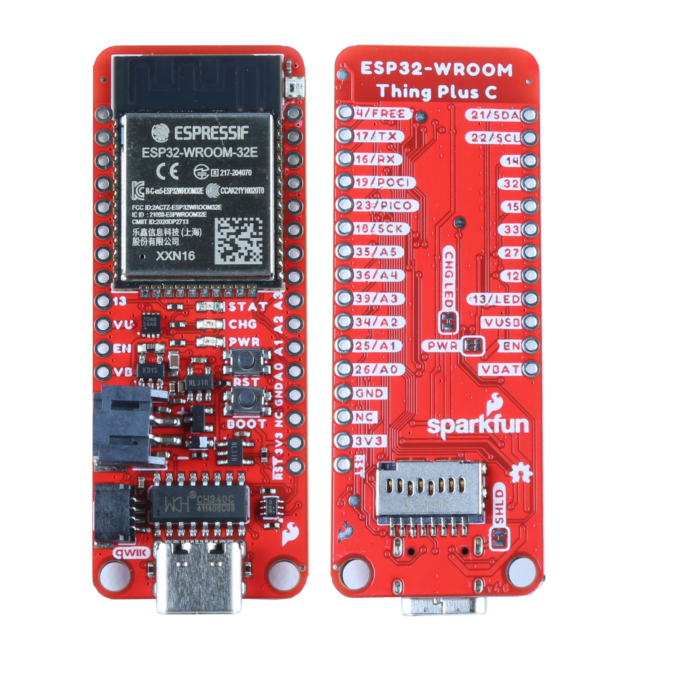
The ESP32-WROOM-32E-N16R2 module:
- 16 MB (Quad SPI) flash memory, 520kB of internal SRAM
- Integrated 802.11 b/g/n WiFi,
- Integrated dual-mode Bluetooth (classic and BLE)
- Hardware accelerated encryption (AES, SHA2, ECC, RSA-4096)
SparkFun exposed/added the following features to the board:
- 21 Multifunctional GPIO
- Up to eight capacitive touch pins
- Up to two I2C Busses
- Up to three SPI Busses
- PWM, 12-bit ADC, DAC, UART
- USB-C Connector
- 2-pin JST Connector for a LiPo Battery as well as a Fuel Gauge (MAX17048)
- 4-pin JST Qwiic Connector
- SD Card Slot
- LEDs:
- Red power LED
- Yellow battery charging indicator
- Programmable Blue status LED
- Programmable RGB LED (WS2812)
SparkFun’s Qwiic Connect System uses 4-pin JST connectors to quickly interface development boards with sensors, LCDs, relays, and more. The ESP32 board uses one of the two I2C buses for Qwiic, which in this application connects the board to the display.
SparkFun 16×2 SerLCD – RGB Text (Qwiic)
This is a simple 16 columns / 2 rows Liquid Crystal Display. It has an ATmega 328P that handles low-level screen control. It connects via serial, I2C, or SPI, but fortunately is also equipped with a Qwiic connector, which reduces the number of wires needed for communication and powering the device. The display requires 3.3V and supports communication baud rates from 1,200 to 1,000,000 (default is set to 9600)
Communicating with the ESP32 board
The CH340 Serial-to-UART chip allows the ESP32 to communicate with a computer through the board’s USB-C connection. However, this requires the installation of the latest drivers, for a computer to recognize the board. E.g., after installing the driver on Mac OS 13, a connected ESP32 board shows up as
/dev/tty.wchusbserial1470
Firmware
MicroPython was already been ported to several ESP32-based boards and to get started we can use just an existing image and flash it onto the device.
Expressive provides esptool.py, a Python-based, open-source, platform-independent utility to communicate with the ROM bootloader in Espressif chips.
The following shows erasing of the firmware on the ESP32, followed by putting the MicroPython firmware on the device.
esptool.py --chip esp32 --port /dev/tty.wchusbserial1470 erase_flash
esptool.py v4.4
Serial port /dev/tty.wchusbserial1470
Connecting......
Chip is ESP32-D0WD-V3 (revision v3.0)
Features: WiFi, BT, Dual Core, 240MHz, VRef calibration in efuse, Coding Scheme None
Crystal is 40MHz
MAC: 94:e6:86:92:d0:a4
Uploading stub...
Running stub...
Stub running...
Erasing flash (this may take a while)...
Chip erase completed successfully in 52.7s
Hard resetting via RTS pin...
esptool.py --chip esp32 -p /dev/tty.wchusbserial1470 write_flash -z 0x1000 ~/Downloads/esp32-20220618-v1.19.1.bin
esptool.py v4.4
Serial port /dev/tty.wchusbserial1470
Connecting.....
Chip is ESP32-D0WD-V3 (revision v3.0)
Features: WiFi, BT, Dual Core, 240MHz, VRef calibration in efuse, Coding Scheme None
Crystal is 40MHz
MAC: 94:e6:86:92:d0:a4
Uploading stub...
Running stub...
Stub running...
Configuring flash size...
Flash will be erased from 0x00001000 to 0x0017efff...
Compressed 1560976 bytes to 1029132...
Wrote 1560976 bytes (1029132 compressed) at 0x00001000 in 90.8 seconds (effective 137.5 kbit/s)...
Hash of data verified.

Leaving...
Hard resetting via RTS pin...
Looking around
Using Mac OS’s screen command to open a communication session, allows us to look at what’s already working on the board:
screen /dev/tty.wchusbserial1470 115200
MPY: soft reboot
MicroPython v1.19.1 on 2022-06-18; ESP32 module with ESP32
Type "help()" for more information.
Software Modules
>>> help('modules')

__main__          gc                ubluetooth        upysh
_boot             inisetup          ucollections      urandom
_onewire          math              ucryptolib        ure
_thread           micropython       uctypes           urequests
_uasyncio         neopixel          uerrno            uselect
_webrepl          network           uhashlib          usocket
apa106            ntptime           uheapq            ussl
btree             onewire           uio               ustruct
builtins          uarray            ujson             usys
cmath             uasyncio/__init__ umachine          utime
dht               uasyncio/core     umqtt/robust      utimeq
ds18x20           uasyncio/event    umqtt/simple      uwebsocket
esp               uasyncio/funcs    uos               uzlib
esp32             uasyncio/lock     upip              webrepl
flashbdev         uasyncio/stream   upip_utarfile     webrepl_setup
framebuf          ubinascii         uplatform         websocket_helper
Plus any modules on the filesystem
Memory
>>> from micro python import men_info
>>> import gc
>>> gc.collect()
>>> mem_info()
stack: 672 out of 15360
GC: total: 111168, used: 1536, free: 109632
No. of 1-blocks: 22, 2-blocks: 6, max blk sz: 18, max free sz: 6780

>>> import esp
>>> esp.flash_size()
4194304

>>> from machine import SDCard
>>> uos.mount(SDCard(slot=2,width=1, cd=None, wp=None,sck=18,miso=19,mosi=23,cs=5,freq=40000000), "/sd")
>>> uos.statvfs("/sd")
(32768, 32768, 243072, 243067, 243067, 0, 0, 0, 0, 255)
>>> uos.statvfs("/")
(4096, 4096, 512, 509, 509, 0, 0, 0, 0, 255)
So the available RAM for Python programs to be used is about 107 KB.
statvfs returns a tuple with the filesystem information in the following order:
f_bsize – file system block size
f_frsize – fragment size
f_blocks – size of fs in f_frsize units
f_bfree – number of free blocks
f_bavail – number of free blocks for unprivileged users
f_files – number of inodes
f_ffree – number of free inodes
f_favail – number of free inodes for unprivileged users
f_flag – mount flags
f_namemax – maximum filename length
Therefore,
number of free blocks * file system block size = 4096 * 509 = 1.9 GB Flash Memory
number of free blocks * file system block size = 32768 * 243067 = 7.4 GB SD Card Memory
Processor Speed
>>> import machine
>>> machine.freq()
160000000
>>> machine.freq(240000000)
>>> machine.freq()
240000000
RGB LED
>>> from machine import Pin
>>> from neopixel import NeoPixel
>>> pin = Pin(2, Pin.OUT)
>>> np = NeoPixel(pin, 1)
>>> np[0] = (255, 255, 255)
>>> np.write()
>>> np[0] = (255, 255,0)
>>> np.write()
>>> np[0] = (0,0,0)
>>> np.write()
I2C
>>> from machine import Pin, I2C
>>> sdaPIN = Pin(21)
>>> sclPIN = Pin(22)
>>> i2c = I2C(0, sda=sdaPIN, scl=sclPIN, freq=400000)
>>> devices = i2c.scan()
>>> devices
[54, 114]
Capacitive touch
from micropython import const
from machine import TouchPad, Pin, Timer


def is_pressed():
    _button = TouchPad(Pin(27))
    _threshold = const(300)
    _pressed = False

    def inner(t: Timer) -> bool:
        nonlocal _pressed
        _pressed = not _pressed and _button.read() < _threshold
        if _pressed:
            print("Pressed")
            return True

    return inner

# The timer period, in milliseconds. The callback must take one argument, which is passed the Timer object
tim = Timer(0)
tim.init(mode=Timer.PERIODIC, period=100, callback=is_pressed())
Pressed
Pressed
Pressed
All in all not too bad. Of the available 16MB flash memory, MicroPython seems to be able to access 2MB. The SDCard (8 GB) is fully accessible.
The processor speed defaults to 16GHz, but can easily be stepped up to the ESP32’s maximum of 24GHz.
Given MicroPython’s built-in support of NeoPixels, the WS2812 RGB already works well – very bright and colorful.
The I2C bus finds the MAX17048 fuel gauge and LCD, but there is more required to access and fully use these devices.
However, to allow full and easy access to the pxBox’s hardware capabilities (flash memory, SDCard, LCD, processor speed, LEDs, etc.) requires a fully customized MicroPython distribution.