ATmega 8 / 168 internal clock and fuse settings
Considering the already low price of the Arduino board, building an Arduino-like board yourself probably doesn’t save you any money but is certainly a fun and education project to do.
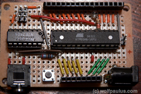
I tried to make the simple board even simpler, by using a Serial instead of an USB Port, the ATmega’s internal clock instead of an external crystal, and requiring 5 VDC instead of providing any kind of power regulation. However, my board does expose the 6 header ICSP, equivalent to the one available on the original Arduino NG Board.
RadioShack’s Multipurpose 417 Holes $1.79 PC Board (Model: 276-150 Catalog: 276-150) built a great starting point for this electronics project, which was obviously inspired by Tom Igoe’s ‘Arduino Breadboard‘.
After soldering the components onto the board and checking all joints, it was time to put the Arduino bootloader into the Flash Ram, which raised a couple system / software related questions I hadn’t thought much about before:
- To be able to use either the ATmega8, which is used on the original Arduino, or the pin compatible ATmega168 microcontroller, which offers twice the amount of internal RAM, I had put a 28-Pin DIP Socket on the board. While the original Arduino board uses an 16.0MHz external crystal, my board relies on the internal clock, which for the ATmega8 means a 1.0MHz Internal RC Oscillator (slowly rising power) and for the ATmega168 an 8.0MHz internal RC oscillator, which by default however gets divided by 8, resulting in 1.0MHz system clock. How could I address the speed difference, to keep software changes to a minimum?
- Since this obviously involved messing with the ATmega’s confusing fuse settings, what fuse bits do I have to adjust?
Let’s address the last question first and take a look at the fuse bytes. The content of those fuse bytes persists reprogramming of the Flash memory and almost every bit in those fuse bytes represent some kind of status setting that configures the microcontroller, for instance to work in concert with other components on the board. Oddly enough, for all fuses ‘1’ means unprogrammed while ‘0’ means programmed.
ATmega’s con- fus(e) -ing settings
| ATmega8 Fuse High Byte | ||||
|---|---|---|---|---|
| Bit | Name | Description | Default (0xD9) | Custom Arduino (0xCA) |
| 7 | RSTDISBL | Select if PC6 is I/O pin or RESET pin | 1 (unprogrammed PC6 is RESET-pin) | 1 |
| 6 | WDTON | WDT always on | 1 (unprogrammed, WDT enabled by WDTCR) | 1 |
| 5 | SPIEN | Enable Serial Program and Data Downloading | 0 (programmed, SPI programming enabled) | 0 |
| 4 | CKOPT | Oscillator options | 1 (unprogrammed) | 0 |
| 3 | EESAVE | EEPROM memory is preserved through the Chip Erase | 1 (unprogrammed, EEPROM not preserved) | 1 |
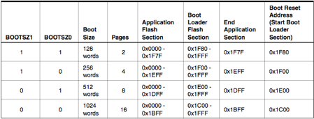
| 2 | BOOTSZ1 | Select Boot Size | 0 (programmed) | 0 |
| 1 | BOOTSZ0 | Select Boot Size | 0 (programmed) | 1 |
| 0 | BOOTRST | Select Reset Vector | 1 (unprogrammed) | 0 |
| ATmega8 Fuse Low Byte | ||||
| Bit | Name | Description | Default (0xE1) | Custom Arduino (0xDF) |
| 7 | BODLEVEL | Brown out detector trigger level | 1 (unprogrammed) | 1 |
| 6 | BODEN | Brown out detector enable | 1 (unprogrammed, no BOD) | 1 |
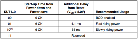
| 5 | SUT1 | Select start-up time | 1 (unprogrammed) | 0 |
| 4 | SUT0 | Select start-up time | 0 (programmed) | 1 |
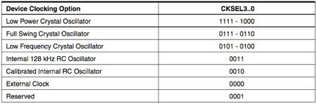
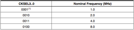
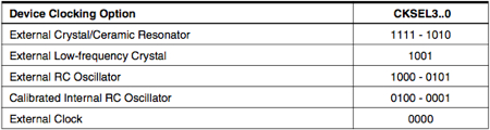
| 3 | CKSEL3 | Select Clock source | 0 (programmed) | 1 |
| 2 | CKSEL2 | Select Clock source | 0 (programmed) | 1 |
| 1 | CKSEL1 | Select Clock source | 0 (programmed) | 1 |
| 0 | CKSEL0 | Select Clock source | 1 (unprogrammed) | 1 |
Looking at my slightly reconfigured Arduino board, I chose the following fuse settings:
High Fuse: 0xDA and Low Fuse: 0xD1, which leaves the ATmega’s Oscillator options at their defaults while allowing the use of the EEPROM and also sets the boot size and boot vector like needed for the Arduino bootloader.
This brings me back to the other question:
How to address the speed difference, to keep software changes to a minimum?
The frequency the ATmega chip is running at, is hardcoded into the bootloader (ATmegaBOOT.c or ATmegaBOOT_168.c). While it is a configuration parameter in the Makefile, putting a bootloader on an Arduino-like board that does not run at 16.0MHz requires adjusting the Makefile and rebuilding the bootloader.
The best place to get Makefile and bootloader source for the ATMega8 is http://svn.berlios.de/viewcvs/arduino/trunk/bootloader/ the same for the ATmega168 can be found here: http://webzone.k3.mah.se/projects/arduino-workshop/upload/default.asp?folder=40
The ATmega8’s Makefile defines DEFS= -DF_CPU=16000000 -DBAUD_RATE=19200 which needs to be modified to DEFS= -DF_CPU=1000000 -DBAUD_RATE=19200
For the ATmega168, make needs to be called with the proper command-line parameters: make PRODUCT=CRUMB168 AVR_FREQ=F1000000 all
The last thing that needs to be done is adjusting the Arduino IDE preferences file: ~/Library/Arduino/preferences.txt on the Mac andC:\Documents and Settings\<USERNAME>\Application Data\Arduino\preferences.txt on Windows:
The build.f_cpu preference needs to be set to 1000000L
For completeness, here are the ATmega 168 fuse bytes, (a couple bits more a.k.a. ‘Extended Fuse Byte’, compared to the ATmega 8).
| ATmega168 Extended Fuse Byte | ||||
|---|---|---|---|---|
| Bit | Name | Description | Default | Custom Arduino |
| 7..3 | not used | N/A | 1 | 1 |
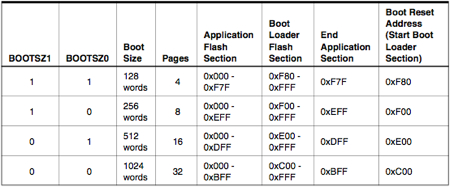
| 2 | BOOTSZ1 | Select Boot Size | 0 (default value of BOOTSZ1..0 results in max. Boot Size | 0 |
| 1 | BOOTSZ0 | Select Boot Size | 0 (default value of BOOTSZ1..0 results in max. Boot Size | 0 |
| 0 | BOOTRST | Select Reset Vector | 1 (unprogrammed) | 0 |
| ATmega168 Fuse High Byte | ||||
| Bit | Name | Description | Default | Custom Arduino |
| 7 | RSTDISBL | External Reset Disable | 1 (unprogrammed PC6 is RESET-pin) | 1 |
| 6 | DWEN | debugWIRE Enable | 1 (unprogrammed) | 1 |
| 5 | SPIEN | Enable Serial Program and Data Downloading | 0 (programmed, SPI programming enabled) | 0 |
| 4 | WDTON | Watchdog Timer Always On | 1 (unprogrammed) | 1 |
| 3 | EESAVE | EEPROM memory is preserved through the Chip Erase | 1 (unprogrammed, EEPROM not preserved) | 0 |
| 2 | BODLEVEL2 | Brown out detector trigger level | 1 (unprogrammed) | 1 |
| 1 | BODLEVEL1 | Brown out detector trigger level | 1 (unprogrammed) | 1 |
| 0 | BODLEVEL0 | Brown out detector trigger level | 1 (unprogrammed) | 1 |
| ATmega168 Fuse Low Byte | ||||
| Bit | Name | Description | Default | Custom Arduino |
| 7 | CKDIV8 | Divide clock by 8 | 0 (programmed) | 1 |
| 6 | CKOUT | Clock output on PORTB0 | 1 (unprogrammed) | 1 |
| 5 | SUT1 | Select start-up time | 1 (unprogrammed) | 0 |
| 4 | SUT0 | Select start-up time | 0 (programmed) | 0 |
| 3 | CKSEL3 | Select Clock source, default for CKSEL3..0 results in intern. 8MHz Oscillator | 0 (programmed) | 0 |
| 2 | CKSEL2 | Select Clock source | 0 (programmed) | 1 |
| 1 | CKSEL1 | Select Clock source | 1 (unprogrammed) | 1 |
| 0 | CKSEL0 | Select Clock source | 0 (programmed) | 1 |